Automated system of operational-remote control of the heat supply process. With the use of modern automation equipment Heating network management system
The introduction of automatic control systems (ACS) for heating, ventilation, hot water supply is the main approach to saving thermal energy. The installation of automatic control systems in individual heat points, according to the All-Russian Thermal Engineering Institute (Moscow), reduces heat consumption in the residential sector by 5-10%, and in administrative premises by 40%. The greatest effect is obtained due to optimal regulation in the spring-autumn period of the heating season, when the automation of central heating points practically does not fully fulfill its functionality. In the conditions of the continental climate of the Southern Urals, when during the day the difference in outside temperature can be 15-20 ° C, the introduction of automatic control systems for heating, ventilation and hot water supply becomes very relevant.
Building thermal management
Management of the thermal regime is reduced to maintaining it at a given level or changing it in accordance with a given law.
At thermal points, mainly two types of heat load are regulated: hot water supply and heating.
For both types of heat load, the ACP must maintain unchanged the setpoints for the temperature of hot water supply water and air in heated rooms.
A distinctive feature of heating regulation is its large thermal inertia, while the inertia of the hot water supply system is much less. Therefore, the task of stabilizing the air temperature in a heated room is much more difficult than the task of stabilizing the temperature of hot water in a hot water supply system.
The main disturbing influences are external meteorological conditions: outdoor temperature, wind, solar radiation.
There are the following fundamentally possible control schemes:
- regulation of the deviation of the internal temperature of the premises from the set one by influencing the flow of water entering the heating system;
- regulation depending on the perturbation of external parameters, leading to a deviation of the internal temperature from the set one;
- regulation depending on changes in the outside temperature and inside the room (by disturbance and by deviation).
Rice. 2.1 Structural diagram of room thermal management by room temperature deviation
On fig. 2.1 shows a block diagram of the control of the thermal regime of the room according to the deviation of the internal temperature of the premises, and in fig. 2.2 shows a block diagram of the control of the thermal regime of the room by perturbation of external parameters.

Rice. 2.2. Structural diagram of the control of the thermal regime of the room by perturbation of external parameters
Internal disturbing effects on the thermal regime of the building are insignificant.
For the disturbance control method, the following signals can be selected as signals to monitor the outside temperature:
- the temperature of the water entering the heating system;
- the amount of heat entering the heating system:
- coolant consumption.
ACP must take into account the following modes of operation of the district heating system, in which:
- the water temperature control at the heat source is not based on the current outdoor temperature, which is the main disturbing factor for the indoor temperature. The temperature of the network water at the heat source is determined by the air temperature over a long period, taking into account the forecast and the available heat output of the equipment. The transport delay, measured by the clock, also leads to a mismatch between the subscriber's network water temperature and the current outdoor temperature;
- hydraulic regimes of heating networks require limiting the maximum and sometimes the minimum consumption of network water for a thermal substation;
- the load of hot water supply has a significant impact on the operating modes of heating systems, leading to variable water temperatures during the day in the heating system or network water consumption for the heating system, depending on the type of heat supply system, the scheme for connecting hot water heaters and the heating scheme.
Disturbance control system
For a disturbance control system, it is characteristic that:
- there is a device that measures the magnitude of the disturbance;
- according to the results of measurements, the controller exercises a control effect on the flow rate of the coolant;
- the controller receives information about the temperature inside the room;
- the main disturbance is the outdoor air temperature, which is controlled by the ACP, so the disturbance will be called controlled.
Variants of control schemes for disturbance with the above tracking signals:
- regulation of the temperature of the water entering the heating system according to the current outdoor temperature;
- regulation of the flow of heat supplied to the heating system according to the current outdoor temperature;
- regulation of network water consumption according to the outdoor air temperature.
As can be seen from Figures 2.1, 2.2, regardless of the method of regulation, the automatic heat supply control system should contain the following main elements:
- primary measuring devices - temperature, flow, pressure, differential pressure sensors;
- secondary measuring devices;
- executive mechanisms containing regulatory bodies and drives;
- microprocessor controllers;
- heating devices (boilers, heaters, radiators).
ASR heat supply sensors
The main parameters of heat supply, which are maintained in accordance with the task with the help of automatic control systems, are widely known.
In heating, ventilation and hot water systems, temperature, flow, pressure, pressure drop are usually measured. In some systems, the heat load is measured. Methods and methods for measuring the parameters of heat carriers are traditional.

Rice. 2.3
On fig. 2.3 shows the temperature sensors of the Swedish company Tour and Anderson.
Automatic regulators
An automatic regulator is an automation tool that receives, amplifies and converts the controlled variable shutdown signal and purposefully influences the regulated object.
Currently, digital controllers based on microprocessors are mainly used. In this case, usually in one microprocessor controller, several regulators for heating, ventilation and hot water supply systems are implemented.
Most domestic and foreign controllers for heat supply systems have the same functionality:
- depending on the outdoor air temperature, the regulator provides the necessary temperature of the heat carrier for heating the building according to the heating schedule, controlling the control valve with an electric drive installed on the heating network pipeline;
- automatic adjustment of the heating schedule is made in accordance with the needs of a particular building. For the greatest efficiency of heat saving, the supply schedule is constantly adjusted taking into account the actual conditions of the heat point, climate, and heat losses in the room;
- the saving of the heat carrier at night is achieved due to the temporary method of regulation. Changing the task for a partial decrease in the coolant depends on the outside temperature so that, on the one hand, reduce heat consumption, on the other hand, do not freeze and warm up the room in time in the morning. At the same time, the moment of turning on the daytime heating mode, or intensive heating, is automatically calculated to achieve the desired room temperature in right time;
- the controllers make it possible to ensure the return water temperature as low as possible. This provides for the protection of the system from freezing;
- the automatic correction set in the hot water system is performed. When the consumption in the domestic hot water system is low, large deviations in temperature are acceptable (increased dead band). This way the valve stem will not be changed too often and its service life will be extended. When the load increases, the dead zone automatically decreases, and the control accuracy increases;
- alarm is triggered when the setpoints are exceeded. The following alarms are usually generated:
- temperature alarm, in case of difference between the real and the set temperature;
- an alarm from the pump comes in case of a malfunction;
- alarm signal from the pressure sensor in the expansion tank;
- a life-of-life alarm is triggered if the equipment has reached its end of life;
- general alarm - if the controller has registered one or more alarms;
- the parameters of the regulated object are registered and transferred to a computer.

Rice. 2.4
On fig. 2.4 microprocessor controllers ECL-1000 from Danfoss are shown.
Regulators
The actuator is one of the links of automatic control systems designed to directly influence the object of regulation. In the general case, the actuating device consists of an actuating mechanism and a regulating body.

Rice. 2.5
The actuator is the drive part of the regulatory body (Fig. 2.5).
In automatic heat supply control systems, mainly electrical (electromagnetic and electric motor) are used.
The regulatory body is designed to change the flow of matter or energy in the object of regulation. There are dosing and throttle regulating bodies. Dosing devices include such devices that change the flow rate of a substance by changing the performance of units (dosers, feeders, pumps).

Rice. 2.6
Throttle regulators (Fig. 2.6) are a variable hydraulic resistance that changes the flow rate of the substance by changing its flow area. These include control valves, elevators, secondary dampers, taps, etc.
Regulators are characterized by many parameters, the main of which are: throughput K v , nominal pressure P y , pressure drop across the regulator D y , and nominal passage D y .
In addition to the above parameters of the regulatory body, which mainly determine their design and dimensions, there are other characteristics that are taken into account when choosing a regulatory body, depending on the specific conditions of their use.
The most important is the flow characteristic, which establishes the dependence of the flow in relation to the movement of the valve at a constant pressure drop.
Throttle control valves are usually profiled with a linear or equal percentage flow characteristic.
With a linear bandwidth characteristic, the increase in bandwidth is proportional to the increment in gate movement.
With an equal-percentage bandwidth characteristic, the bandwidth increment (when the shutter movement changes) is proportional to the current bandwidth value.
Under operating conditions, the type of flow characteristic changes depending on the pressure drop across the valve. When assisted, the control valve is characterized by a flow characteristic, which is the dependence of the relative flow rate of the medium on the degree of opening of the regulating body.
The smallest value of the throughput, at which the throughput characteristic remains within the specified tolerance, is evaluated as the minimum throughput.
In many industrial process automation applications, the regulator must have a wide range of throughput, which is the ratio of the nominal throughput to the minimum throughput.
A necessary condition for the reliable operation of an automatic control system is right choice flow characteristics of the control valve.
For a specific system, the flow characteristic is determined by the values of the parameters of the medium flowing through the valve and its throughput characteristic. In general, the flow characteristic differs from the flow characteristic, since the parameters of the medium (mainly pressure and pressure drop) usually depend on the flow rate. Therefore, the task of choosing the preferred flow characteristics of the control valve is divided into two stages:
- form selection flow characteristics, which ensures the constancy of the transmission coefficient of the control valve over the entire load range;
- selection of the form of the throughput characteristic, which provides the desired form of the flow characteristic for the given parameters of the medium.
When modernizing heating, ventilation and hot water supply systems, the dimensions of a typical network, the available pressure and the initial pressure of the medium are specified, the regulating body is chosen so that at a minimum flow rate through the valve, the loss in it corresponds to the excess pressure of the medium developed by the source, and the shape of the flow characteristic is close to given. The method of hydraulic calculation when choosing a control valve is quite laborious.
AUZhKH trust 42, in collaboration with SUSU, has developed a program for calculating and selecting regulatory bodies for the most common heating and hot water supply systems.
Circular pumps
Regardless of the scheme for connecting the heat load, a circulation pump is installed in the heating system circuit (Fig. 2.7).

Rice. 2.7. Circular pump (Grundfog).
It consists of a speed controller, an electric motor and the pump itself. The modern circulation pump is a glandless pump with a wet rotor that does not require maintenance. The engine control is usually carried out by an electronic speed controller designed to optimize the performance of the pump operating in conditions of increased external disturbances affecting the heating system.
The action of the circulation pump is based on the dependence of the pressure on the performance of the pump and, as a rule, has a quadratic character.
Circulation pump parameters:
- performance;
- maximum pressure;
- speed;
- speed range.
AUZhKH trust 42 has the necessary information on the calculation and selection of circulation pumps and can provide the necessary advice.
Heat exchangers
The most important elements of heat supply are heat exchangers. There are two types of heat exchangers: tubular and plate. Simplified, a tubular heat exchanger can be represented as two pipes (one pipe is inside the other rough). The plate heat exchanger is a compact heat exchanger assembled on a suitable frame of corrugated plates fitted with seals. Tubular and plate heat exchangers are used for hot water supply, heating and ventilation. The main parameters of any heat exchanger are:
- power;
- heat transfer coefficient;
- loss of pressure;
- maximum operating temperature;
- maximum working pressure;
- maximum flow.
Shell-and-tube heat exchangers have low efficiency due to low water flow rates in the tubes and annulus. This leads to low values of the heat transfer coefficient and, as a result, unreasonably large dimensions. During the operation of heat exchangers, significant deposits in the form of scale and corrosion products are possible. In shell-and-tube heat exchangers, the elimination of deposits is very difficult.
Compared to tube heat exchangers, plate heat exchangers differ increased efficiency by improving heat transfer between the plates, in which turbulent coolant flows countercurrently. In addition, the repair of the heat exchanger is quite simple and inexpensive.
Plate heat exchangers successfully solve the problems of preparing hot water in heating points with virtually no heat loss, so they are actively used today.
The principle of operation of plate heat exchangers is as follows. The liquids involved in the heat transfer process are introduced through the nozzles into the heat exchanger (Fig. 2.8).

Rice. 2.8
Gaskets, installed in a special way, ensure the distribution of liquids in the appropriate channels, eliminating the possibility of mixing flows. The type of corrugations on the plates and the configuration of the channel are selected in accordance with the required amount of free passage between the plates, thereby ensuring optimal conditions heat exchange process.

Rice. 2.9
The plate heat exchanger (Fig. 2.9) consists of a set of corrugated metal plates with holes in the corners for the passage of two fluids. Each plate is equipped with a gasket that limits the space between the plates and ensures the flow of liquids in this channel. Heat carrier consumption, physical properties liquids, pressure loss and temperature conditions determine the number and size of the plates. Their corrugated surface contributes to an increase in turbulent flow. Contacting in intersecting directions, the corrugations support the plates, which are under conditions of different pressure from both coolants. To change the capacity (increase the heat load), a certain number of plates must be added to the heat exchanger package.
Summing up the above, we note that the advantages of plate heat exchangers are:
- compactness. Plate heat exchangers are more than three times more compact than shell and tube heat exchangers and more than six times lighter at the same power;
- ease of installation. Heat exchangers do not require a special foundation;
- low maintenance costs. The highly turbulent flow results in a low degree of pollution. New models of heat exchangers are designed in such a way as to extend the period of operation, which does not require repair, as much as possible. Cleaning and checking takes little time, since in the heat exchangers each heating sheet is taken out, which can be cleaned individually;
- effective use thermal energy. The plate heat exchanger has a high heat transfer coefficient, transfers heat from the source to the consumer with low losses;
- reliability;
- the ability to significantly increase the thermal load by adding a certain number of plates.
The temperature regime of the building as an object of regulation
When describing the technological processes of heat supply, design schemes of statics are used, which describe steady states, and design schemes of dynamics, which describe transient conditions.
The design schemes of the heat supply system determine the relationship between the input and output effects on the control object under the main internal and external disturbances.
A modern building is a complex heat and power system; therefore, simplifying assumptions are introduced to describe the temperature regime of a building.
- For multi-storey civil buildings, the part of the building for which the calculation is made is localized. Since the temperature regime in the building varies depending on the floor, the horizontal layout of the premises, the temperature regime is calculated for one or more of the most favorably located premises.
- The calculation of convective heat transfer in a room is derived from the assumption that the air temperature at each moment of time is the same throughout the entire volume of the room.
- When determining heat transfer through external enclosures, it is assumed that the enclosure or its characteristic part have the same temperature in planes perpendicular to the direction of air flow. Then the process of heat transfer through the outer enclosures will be described by a one-dimensional heat conduction equation.
- The calculation of radiant heat transfer in a room also allows a number of simplifications:
a) we consider the air in the room to be a radiant medium;
b) we neglect multiple reflections of radiant fluxes from surfaces;
c) complex geometric shapes are replaced by simpler ones. - Outdoor climate parameters:
a) if the temperature regime of the premises is calculated at extreme values of the outdoor climate indicators that are possible in a given area, then the thermal protection of the fences and the power of the microclimate control system will ensure stable compliance with the specified conditions;
b) if we accept softer requirements, then in the room at some points in time there will be deviations from the design conditions.
Therefore, when assigning the design characteristics of the outdoor climate, it is mandatory to take into account the security of internal conditions.
AUZhKH Trust 42 specialists, together with SUSU scientists, have developed a computer program for calculating static and dynamic operating modes of subscriber bushings.

Rice. 2.10
On fig. 2.10 shows the main disturbing factors acting on the object of regulation (room). The heat Q source, coming from the heat source, performs the functions of a control action to maintain the room temperature T pom at the outlet of the object. Outside temperature T nar, wind speed V wind, solar radiation J rad, internal heat loss Q inside are disturbing influences. All these effects are functions of time and are random. The task is complicated by the fact that heat transfer processes are non-stationary and are described by differential equations in partial derivatives.
Below is a simplified design scheme of the heating system, which accurately describes the static thermal conditions in the building, and also allows you to qualitatively assess the impact of the main disturbances on the dynamics of heat transfer, to implement the main methods for regulating the processes of space heating.
Currently, studies of complex nonlinear systems (these include heat transfer processes in a heated room) are carried out using mathematical modeling methods. The use of computer technology to study the dynamics of the space heating process and possible control methods is an effective and convenient engineering method. The effectiveness of modeling lies in the fact that the dynamics of a complex real system can be studied using relatively simple application programs. Mathematical modeling allows you to explore the system with continuously changing its parameters, as well as perturbing influences. The use of modeling software packages for studying the heating process is especially valuable, since the study by analytical methods turns out to be very laborious and completely unsuitable.

Rice. 2.11
On fig. 2.11 shows fragments of the design scheme of the static mode of the heating system.
The figure has the following symbols:
- t 1 (T n) - the temperature of the network water in the supply line of the power network;
- T n (t) - outdoor temperature;
- U - mixing ratio of the mixing unit;
- φ - relative consumption of network water;
- ΔT - design temperature difference in the heating system;
- δt is the calculated temperature difference in the heating network;
- T in - internal temperature of heated premises;
- G - consumption of network water at the heating point;
- D p - water pressure drop in the heating system;
- t - time.
With subscriber input with installed equipment for given calculated heating load Q 0 and daily schedule of hot water supply load Q r, the program allows you to solve any of the following tasks.
At an arbitrary outdoor temperature T n:
- determine the internal temperature of the heated premises T in, while the specified are the flow of network water or the input G with and the temperature graph in the supply line;
- determine the consumption of network water for input G c, required to provide a given internal temperature of heated premises T in with a known temperature graph of the heating network;
- determine the required water temperature in the supply line of the heating network t 1 (network temperature graph) to ensure the specified internal temperature of heated rooms T in at a given flow rate of network water G s. These tasks are solved for any heating system connection scheme (dependent, independent) and any hot water supply connection scheme (series, parallel, mixed).
In addition to the above parameters, water flow rates and temperatures are determined at all characteristic points of the scheme, heat flow rates for the heating system and thermal loads of both stages of the heater, and pressure losses of heat carriers in them. The program allows you to calculate the modes of subscriber inputs with any type of heat exchangers (shell and tube or plate).

Rice. 2.12
On fig. 2.12 shows fragments of the design scheme of the dynamic mode of the heating system.
The program for calculating the dynamic thermal regime of the building allows for subscriber input with the selected equipment for a given design heating load Q 0 to solve any of the following tasks:
- calculation of the control scheme for the thermal regime of the room according to the deviation of its internal temperature;
- calculation of the control scheme for the thermal regime of the room according to the perturbation of external parameters;
- calculation of the thermal regime of the building with qualitative, quantitative and combined methods of regulation;
- calculation of the optimal controller with non-linear static characteristics of real elements of the system (sensors, control valves, heat exchangers, etc.);
- with an arbitrarily time-varying outdoor temperature T n (t), it is necessary:
- determine the change in time of the internal temperature of the heated premises T in;
- determine the change in time of the flow of network water pa input G with required to provide a given internal temperature of the heated premises T in with an arbitrary temperature graph of the heating network;
- determine the change in time of the water temperature in the supply line of the heating network t 1 (t).
These tasks are solved for any heating system connection scheme (dependent, independent) and any hot water supply connection scheme (series, parallel, mixed).
Implementation of ASR for heat supply in residential buildings

Rice. 2.13
On fig. 2.13 shows a schematic diagram of an automatic control system for heating and hot water supply in an individual heating point (ITP) with dependent connection of the heating system and a two-stage scheme of hot water heaters. It was mounted by AUZhKH trust 42, passed tests and operational checks. This system applicable to any connection scheme for heating and hot water systems of this type.
The main task of this system is to maintain a given dependence of the change in the consumption of network water for the heating and hot water supply system on the outside air temperature.
The connection of the heating system of the building to the heating networks is made according to a dependent scheme with pump mixing. For the preparation of hot water for the needs of hot water supply, it is planned to install plate heaters connected to the heating network according to a mixed two-stage scheme.
The heating system of the building is a two-pipe vertical system with a lower distribution of main pipelines.
The building's automatic heat supply control system includes solutions for:
- for automatic control of the operation of the external heat supply circuit;
- for automatic control of the operation of the internal circuit of the heating system of the building;
- to create a mode of comfort in the premises;
- for automatic control of the operation of the DHW heat exchanger.
The heating system is equipped with a microprocessor-based water temperature controller for the heating circuit of the building (internal circuit), complete with temperature sensors and a motorized control valve. Depending on the outside air temperature, the control device ensures the required temperature of the coolant for heating the building according to the heating schedule, controlling the control valve with an electric drive installed on a direct pipeline from the heating network. To limit the maximum temperature of the return water returned to the heating network, a signal from a temperature sensor installed on the return water pipeline to the heating network is input to the microprocessor controller. The microprocessor controller protects the heating system from freezing. To maintain a constant differential pressure, a differential pressure regulator is provided on the temperature control valve.
To automatically control the air temperature in the premises of the building, the project provides for thermostats on heating devices. Thermoregulators provide comfort and save heat energy.
To maintain a constant differential pressure between the direct and return pipelines of the heating system, a differential pressure regulator is installed.
To automatically control the operation of the heat exchanger, an automatic temperature controller is installed on the heating water, which changes the supply of heating water depending on the temperature of the heated water entering the DHW system.
In accordance with the requirements of the "Rules for accounting for thermal energy and coolant" of 1995, commercial accounting of thermal energy was carried out at the input of the heating network to the ITP by means of a heat meter installed on the supply pipeline from the heating network and a volume meter installed on the return pipeline to the heating network.
The heat meter includes:
- flowmeter;
- CPU;
- two temperature sensors.
The microprocessor controller provides indication of parameters:
- quantity of heat;
- the amount of coolant;
- coolant temperature;
- temperature difference;
- operating time of the heat meter.
All elements of automatic control systems and hot water supply are made using Danfoss equipment.
The ECL 9600 microprocessor controller is designed to control the temperature regime of water in heating and hot water supply systems in two independent circuits and is used for installation at heating points.
The regulator has relay outputs for controlling control valves and circulation pumps.
Items to be connected to the ECL 9600 controller:
- outdoor air temperature sensor ESMT;
- temperature sensor at the coolant supply in the circulation circuit 2, ESMA/C/U;
- reversible drive of the control valve of the AMB or AMV series (220 V).
In addition, the following elements can be attached optionally:
- return water temperature sensor from the circulation circuit, ESMA/C/U;
- ESMR indoor air temperature sensor.
The ECL 9600 microprocessor controller has built-in analog or digital timers and an LCD display for easy maintenance.
The built-in indicator serves for visual observation of parameters and adjustment.
When an ESMR/F indoor air temperature sensor is connected, the temperature of the heating medium is automatically corrected at the supply to the heating system.
The controller can limit the value of the return water temperature from the circulation circuit in follow-up mode depending on the outdoor temperature (proportional limitation) or set a constant value for the maximum or minimum limitation of the return water temperature from the circulation circuit.
Comfort and heat saving features:
- lowering the temperature in the heating system at night and depending on the outdoor temperature or according to the set reduction value;
- the possibility of operating the system with increased power after each period of temperature decrease in the heating system (quick heating of the room);
- the possibility of automatic shutdown of the heating system at a certain set outdoor temperature (summer shutdown);
- opportunity to work with various types mechanized control valve drives;
- remote control regulator using ESMF/ECA 9020.
Protective features:
- limiting the maximum and minimum temperatures of the water supplied to the circulation circuit;
- pump control, periodic change in summer period;
- protection of the heating system from freezing;
- the possibility of connecting a safety thermostat.
Modern equipment for automatic heat supply control systems
Domestic and foreign firms provide big choice modern equipment automatic heat supply control systems with almost the same functionality:
- Heating control:
- Damping outdoor temperature.
- Monday Effect.
- Linear restrictions.
- Return temperature limits.
- Room temperature correction.
- Self-correcting feed schedule.
- Startup time optimization.
- Economy mode at night.
- DHW management:
- Low load feature.
- Return water temperature limit.
- Separate timer.
- Pump control:
- Freeze protection.
- Turn off the pump.
- Pump exchange.
- Alarms:
- From the pump.
- Freezing temperature.
- General.
Sets of heat supply equipment from well-known companies, Danfoss (Denmark), Alfa Laval (Sweden), Tour and Anderson (Sweden), Raab Karcher (Germany), Honeywell (USA) generally include the following instruments and devices for control and accounting systems.
- Automation equipment heating point building:

- Heat metering equipment.

- Auxiliary equipment.
- Check valves.
- Ball valves are installed for hermetic shutdown of risers and for draining water. At the same time, in the open state, during the operation of the system, ball valves practically do not create additional resistance. They can also be installed on all branches at the entrance to the building and at the substation.
- Drain ball valves.
- A non-return valve is installed to prevent water from entering the return line from the supply line when the pump is stopped.
- The mesh filter, with a ball valve on the drain, at the inlet to the system provides water purification from solid suspensions.
- Automatic air vents provide automatic air release when filling the heating system, as well as during the operation of the heating system.
- Radiators.
- Convectors.
- Intercoms ("Vika" AUZhKH trust 42).
The AUZhKH of trust 42 analyzed the functionality of the equipment of automatic heat supply control systems of the most famous companies: Danfoss, Tour and Anderson, Honeywell. Employees of the trust can provide qualified advice on the implementation of the equipment of these firms.
The peculiarities of heat supply are the rigid mutual influence of heat supply and heat consumption modes, as well as the multiplicity of supply points for several goods (thermal energy, power, coolant, hot water). The purpose of heat supply is not to provide generation and transport, but to maintain the quality of these goods for each consumer.
This goal was achieved relatively effectively with stable coolant flow rates in all elements of the system. The “quality” regulation we use, by its very nature, implies changing only the temperature of the coolant. The emergence of demand-controlled buildings ensured the unpredictability of hydraulic regimes in networks while maintaining the constancy of costs in the buildings themselves. Complaints in the neighboring houses had to be eliminated by excessive circulation and the corresponding mass overflows.
The hydraulic calculation models used today, despite their periodic calibration, cannot provide for accounting for deviations in costs at building inputs due to changes in internal heat generation and hot water consumption, as well as the influence of sun, wind and rain. With the actual qualitative-quantitative regulation, it is necessary to “see” the system in real time and provide:
- control of the maximum number of delivery points;
- reconciliation of current balances of supply, losses and consumption;
- control action in case of unacceptable violation of modes.
Management should be as automated as possible, otherwise it is simply impossible to implement it. The challenge was to achieve this without undue expense of setting up checkpoints.
Today, when in a large number of buildings there are measuring systems with flow meters, temperature and pressure sensors, it is unreasonable to use them only for financial calculations. ACS "Teplo" is built mainly on the generalization and analysis of information "from the consumer".
When creating the automated control system, typical problems of outdated systems were overcome:
- dependence on the correctness of calculations of metering devices and the reliability of data in unverifiable archives;
- the impossibility of bringing together operational balances due to inconsistencies in the time of measurements;
- inability to control rapidly changing processes;
- non-compliance with new requirements information security federal law"On the safety of critical information infrastructure Russian Federation".
Effects from the implementation of the system:
Consumer Services:
- determination of real balances for all types of goods and commercial losses:
- determination of possible off-balance sheet income;
- control of actual power consumption and its compliance with technical specifications for connection;
- introduction of restrictions corresponding to the level of payments;
- transition to a two-part tariff;
- monitoring KPIs for all services working with consumers and assessing the quality of their work.
Exploitation:
- determination of technological losses and balances in heat networks;
- dispatching and emergency control according to actual modes;
- maintaining optimal temperature schedules;
- monitoring the state of networks;
- adjustment of heat supply modes;
- control of shutdowns and violations of modes.
Development and investment:
- reliable assessment of the results of the implementation of improvement projects;
- assessment of the effects of investment costs;
- development of heat supply schemes in real electronic models;
- optimization of diameters and network configuration;
- reduction of connection costs, taking into account the real reserves of bandwidth and energy savings for consumers;
- renovation planning
- organization of joint work of CHP and boiler houses.
Modernization and Automation of Heat Supply System Minsk experiencce
V.A. Sednin, Scientific Consultant, Doctor of Engineering, Professor,
A.A. Gutkovskiy, Chief Engineer, Belorussian National Technicl University, Scientific Research and Innovations Center of Automated Control Systems in heat power industry
keywords: heat supply system, automated control systems, reliability and quality improvement, heat delivery regulation, data archiving
Heat supply of large cities in Belorussia, as in Russia, is provided by cogeneration and district heat supply systems (hereinafter - DHSS), where facilities are combined into a single system. However, often the decisions made on individual elements of complex heat supply systems do not meet the systematic criteria, reliability, controllability and environment protection requirements. Therefore modernization of the heat supply systems and creation of automated process control systems is the most relevant task.
Description:
V.A. Sednin, A.A. Gutkovsky
The heat supply of large cities of Belarus, as in Russia, is provided by heating and district heating systems (hereinafter referred to as DH), the facilities of which are linked into a single scheme. However, decisions made on individual elements of complex heat supply systems often do not meet system criteria, reliability, manageability and environmental friendliness requirements. Therefore, the modernization of heat supply systems and the creation of automated control systems technological processes is the most pressing issue.
V. A. Sednin, scientific consultant, doctor of tech. sciences, professor
A. A. Gutkovsky, Chief Engineer, Belarusian National Technical University, Research and Innovation Center for Automated Control Systems in Heat Power and Industry
Heat supply to large cities of Belarus, as in Russia, is provided by district heating and district heating systems (DH) whose facilities are linked into a single scheme. However, decisions made on individual elements of complex heat supply systems often do not meet system criteria, reliability, manageability and environmental friendliness requirements. Therefore, the modernization of heat supply systems and the creation of automated process control systems is the most urgent task.
Features of district heating systems
Considering the main features of the SDT of Belarus, it can be noted that they are characterized by:
- continuity and inertia of its development;
- territorial distribution, hierarchy, variety of technical means used;
- dynamic production processes and stochastic energy consumption;
- incompleteness and low degree of reliability of information about the parameters and modes of their functioning.
It is important to note that in the SCT heating network, unlike other pipeline systems, are used to transport not the product, but the energy of the coolant, the parameters of which must meet the requirements of various consumer systems.
These features emphasize the essential need for the creation of automated process control systems (hereinafter referred to as APCS), the implementation of which makes it possible to increase energy and environmental efficiency, reliability and quality of functioning of heat supply systems. The introduction of automated process control systems today is not a tribute to fashion, but follows from the basic laws of the development of technology and is economically justified at the present stage of development of the technosphere.
| REFERENCE |
The district heating system of Minsk is a structurally complex complex. In terms of production and transport of thermal energy, it includes the facilities of Minskenergo RUE (Minsk Heat Networks, heating complexes of CHPP-3 and CHPP-4) and the facilities of Minskkommunteploset Unitary Enterprise - boiler houses, heat networks and central heating points. Creation of APCS UE "Minskkommunteploset" was started in 1999, and now it is functioning, covering almost all heat sources (over 20) and a number of districts of heat networks. The development of the APCS project for the Minsk Heat Networks was launched in 2010, the project implementation began in 2012 and is currently ongoing. |
Development of an automated process control system for the heat supply system in Minsk
On the example of Minsk, we present the main approaches that have been implemented in a number of cities in Belarus and Russia in the design and development of process control systems for heat supply systems.
Taking into account the vastness of issues covering the subject area of heat supply, and the accumulated experience in the field of automation of heat supply systems at the pre-project stage of creating an automated control system for Minsk heat networks, a concept was developed. The concept defines the fundamental foundations of the organization of automated process control systems for heat supply in Minsk (see reference) as a process of creating a computer network (system) focused on automating technological processes of a topologically distributed district heating enterprise.
Technological information tasks of process control systems
The implemented automated control system primarily provides for increasing the reliability and quality of operational control of the modes of operation of individual elements and the heat supply system as a whole. Therefore, this process control system is designed to solve the following technological information problems:
- provision of centralized functional-group control of hydraulic regimes of heat sources, main heat networks and pumping stations, taking into account daily and seasonal changes in circulation costs with adjustment (feedback) according to actual hydraulic regimes in the distribution heat networks of the city;
- implementation of the method of dynamic central control of heat supply with optimization of heat carrier temperatures in the supply and return pipelines of heating mains;
- ensuring the collection and archiving of data on the thermal and hydraulic modes of operation of heat sources, main heating networks, a pumping station and distribution heating networks of the city for monitoring, operational management and analysis of the functioning of the Minsk heating networks' central heating system;
- creation of an effective system for protecting equipment of heat sources and heating networks in emergency situations;
creation of an information base for solving optimization problems arising in the course of operation and modernization of objects of the Minsk heat supply system.
| REFERENCE 1 |
The structure of the Minsk thermal networks includes 8 network districts (RTS), 1 thermal power plant, 9 boiler houses with a capacity of several hundred to a thousand megawatts. In addition, 12 step-down pumping stations and 209 central heating stations are serviced by the Minsk Heat Networks. Organizational and production structure of the Minsk heat networks according to the "bottom-up" scheme:
|

The structure of the automated process control system of Minsk heating networks
In accordance with the production and organizational structure of the Minsk Heat Networks (see Reference 1), a four-level structure of the APCS of the Minsk Heat Networks was chosen:
- the first (upper) level is the central control room of the enterprise;
- the second level - operator stations of districts of thermal networks;
- third level - operator stations of heat sources (operator stations of workshop sections of heating networks);
- fourth (lower) level - stations for automatic control of installations (boiler units) and processes of transport and distribution of thermal energy (technological scheme of a heat source, heating points, heating networks, etc.).
The development (creation of an automated process control system for heat supply of the entire city of Minsk) involves the inclusion in the system at the second structural level of operator stations of heating complexes of Minsk CHPP-2, CHPP-3, CHPP-4 and an operator station (central dispatching room) of UE "Minskkommunteploset". All management levels are planned to be combined into a single computer network.
The architecture of the process control system for the heat supply system of Minsk
The analysis of the control object as a whole and the state of its individual elements, as well as the prospects for the development of the control system, made it possible to propose the architecture of a distributed automated process control system for the Minsk heat supply system within the facilities of RUE "Minskenergo". Corporate network integrates the computing resources of the central office and remote structural divisions, including automatic control stations (ACS) of network area objects. All ACS (TsTP, ITP, PNS) and scanning stations are connected directly to the operator stations of the respective network areas, presumably installed at master sites.
On the remote structural unit(for example, RTS-6) the following stations are installed (Fig. 1): operator station "RTS-6" (OPS RTS-6) - it is the control center of the network area and is installed on the master section of RTS-6. For operational personnel, RTS-6 provides access to all information and control resources of ACS of all types without exception, as well as access to authorized information resources of the central office. OpS RTS-6 provide regular scanning of all slave control stations.
The operational and commercial information collected from all central heating centers is sent for storage to a dedicated database server (installed in the immediate vicinity of the RTS-6 OpS).
Thus, taking into account the scale and topology of the control object and the existing organizational and production structure of the enterprise, the APCS of the Minsk Heat Networks is built according to a multi-link scheme using a hierarchical structure of software and hardware and computer networks that solve various control tasks at each level.
Management system levels
At the lower level, the control system performs:
- preliminary processing and transmission of information;
- regulation of the main technological parameters, functions of control optimization, protection of technological equipment.
TO technical means the lower level is subject to increased reliability requirements, including the possibility of autonomous operation in case of loss of communication with the upper level computer network.
The subsequent levels of the control system are built according to the hierarchy of the heat supply system and solve the tasks of the corresponding level, as well as provide an operator interface.
Control devices installed at facilities, in addition to their direct duties, should also provide for the possibility of aggregating them into distributed control systems. The control device must ensure the operability and safety of the information of objective primary accounting during long interruptions in communication.
The main elements of such a scheme are technological and operator stations interconnected by communication channels. The core of the technological station should be an industrial computer equipped with means of communication with the control object and channel adapters for organizing interprocessor communication. The main purpose of the technological station is the implementation of direct digital control algorithms. In technically justified cases, some functions can be performed in supervisory mode: the process station processor can control remote intelligent controllers or software logic modules using modern field interface protocols.
Informational aspect of building an automated process control system for heat supply
Particular attention during the development was paid to the informational aspect of building an automated process control system for heat supply. The completeness of the description of the production technology and the perfection of information conversion algorithms are the most important part information support APCS built on direct digital control technology. The information capabilities of the automated process control system for heat supply provide the ability to solve a set of engineering problems that classify:
- by stages of the main technology (production, transport and consumption of thermal energy);
- by purpose (identification, forecasting and diagnostics, optimization and management).
When creating an automated process control system for Minsk heating networks, it is planned to form information field, allowing you to quickly solve the entire complex of the above problems of identification, forecasting, diagnostics, optimization and management. At the same time, information provides the possibility of solving systemic problems of the upper level of management with the further development and expansion of automated process control systems as the relevant technical services for the main technological process are included.
In particular, this applies to optimization tasks, i.e., optimization of the production of thermal and electrical energy, modes of supply of thermal energy, flow distribution in thermal networks, operating modes of the main technological equipment of heat sources, as well as calculating the rationing of fuel and energy resources, energy accounting and operation, planning and forecasting the development of the heat supply system. In practice, the solution of some problems of this type is carried out within the framework of the enterprise automated control system. In any case, they must take into account the information obtained in the course of solving the problems of directly controlling the technological process, and the information system created by the process control system must be integrated with other information systems enterprises.
Methodology of software-object programming
Building software control system, which is an original development of the center team, is based on the methodology of program-object programming: in the memory of control and operator stations, program objects are created that display real processes, units and measuring channels of an automated technological object. The interaction of these software objects (processes, aggregates and channels) with each other, as well as with operational personnel and with technological equipment, in fact, ensures the functioning of the elements of heat networks according to predefined rules or algorithms. Thus, the description of algorithms is reduced to the description of the most essential properties of these program objects and the ways of their interaction.
The synthesis of the structure of the control system of technical objects is based on the analysis of the technological scheme of the control object and a detailed description of the technology of the main processes and functioning inherent in this object as a whole.
A convenient tool for compiling this type of description for heat supply facilities is the methodology of mathematical modeling at the macro level. In the course of compiling a description of technological processes, a mathematical model is compiled, a parametric analysis is performed, and a list of adjustable and controlled parameters and regulatory bodies is determined.
The regime requirements of technological processes are specified, on the basis of which the boundaries of the permissible ranges for changing the regulated and controlled parameters and the requirements for the choice of actuators and regulatory bodies are determined. Based on the generalized information, the synthesis of an automated object control system is carried out, which, when using the direct digital control method, is built according to a hierarchical principle in accordance with the hierarchy of the control object.
ACS of the district boiler house
So, for a district boiler house (Fig. 2), an automated control system is built on the basis of two classes.
The upper level is the operator station "Boiler" (OPS "Boiler") - the main station that coordinates and controls the subordinate stations. Fire station “Boiler reserve” is a hot standby station, which is constantly in the mode of listening and registering the traffic of the main fire station and its subordinate ACS. Its database contains up-to-date parameters and complete historical data on the functioning of the working control system. At any time, a backup station can be assigned as the main station with full traffic transfer to it and the permission of supervisory control functions.
The lower level is a complex of automatic control stations united together with the operator station in a computer network:
- ACS "Boiler unit" provides control of the boiler unit. As a rule, it is not reserved, since the reservation of the thermal power of the boiler house is carried out at the level of boiler units.
- ACS "Grid Group" is responsible for the thermal-hydraulic mode of operation of the boiler house (control of a group of network pumps, bypass line at the outlet of the boiler room, bypass line, inlet and outlet valves of boilers, individual boiler recirculation pumps, etc.).
- SAU "Vodopodgotovka" provides control of all auxiliary equipment of the boiler house, necessary for feeding the network.
For simpler objects of the heat supply system, for example, heat points and block boiler houses, the control system is built as a single-level one based on an automatic control station (SAU TsTP, SAU BMK). In accordance with the structure of heat networks, the control stations of heat points are combined into a local area network of the heat network area and are connected to the operator station of the heat network area, which, in turn, has an information connection with the operator station for more than high level integration.
Operator stations
The software of the operator station provides a friendly interface for the operating personnel controlling the operation of the automated technological complex. Operator stations have advanced means of operational dispatch control, as well as mass memory devices for organizing short-term and long-term archives of the state of the parameters of the technological control object and the actions of operational personnel.
In cases of large information flows that are closed to operational personnel, it is advisable to organize several operator stations with the allocation of a separate database server and, possibly, a communication server.
The operator station, as a rule, does not directly affect the control object itself - it receives information from technological stations and also transmits directives to the operating personnel or tasks (settings) of supervisory control, generated automatically or semi-automatically. It forms workplace operator of a complex object, such as a boiler room.
The automated control system being created provides for the construction of an intelligent superstructure, which should not only track disturbances that occur in the system and respond to them, but also predict the occurrence of emergency situations and block their occurrence. When changing the topology of the heat supply network and the dynamics of its processes, it is possible to adequately change the structure of the distributed control system by adding new control stations and (or) changing software objects without changing the equipment configuration of existing stations.
Efficiency of APCS of the heat supply system
An analysis of the operating experience of automated process control systems for heat supply enterprises 1 in a number of cities in Belarus and Russia, conducted over the past twenty years, showed them economic efficiency and confirmed the viability decisions taken architecture, software and hardware.
In terms of their properties and characteristics, these systems meet the requirements of the ideology of smart grids. Nevertheless, work is constantly underway to improve and develop the developed automated control systems. The introduction of automated process control systems for heat supply increases the reliability and efficiency of the DH operation. The main saving of fuel and energy resources is determined by the optimization of the thermal-hydraulic modes of heating networks, the operating modes of the main and auxiliary equipment of heat sources, pumping stations and heating points.
Literature
- Gromov N.K. Urban heating systems. M. : Energy, 1974. 256 p.
- Popyrin L. S. Research of heat supply systems. M. : Nauka, 1989. 215 p.
- Ionin A. A. Reliability of systems of thermal networks. Moscow: Stroyizdat, 1989. 302 p.
- Monakhov G. V. Modeling of control modes of heat networks. M.: Energoatomizdat, 1995. 224 p.
- Sednin VA Theory and practice of creating automated heat supply control systems. Minsk: BNTU, 2005. 192 p.
- Sednin V. A. Implementation of automated process control systems as a fundamental factor in improving the reliability and efficiency of heat supply systems // Technology, equipment, quality. Sat. mater. Belarusian Industrial Forum 2007, Minsk, May 15–18, 2007 / Expoforum – Minsk, 2007, pp. 121–122.
- Sednin V. A. Optimization of the parameters of the temperature graph of heat supply in heating systems // Energetika. News of higher educational institutions and energy associations of the CIS. 2009. No. 4. S. 55–61.
- Sednin V. A. The concept of creating an automated process control system for Minsk heat networks / V. A. Sednin , A. V. Sednin, E. O. Voronov // Improving the efficiency of power equipment: Proceedings of the scientific and practical conference, in 2 v. T. 2. 2012. S. 481–500.
1 Created by a team of Research and Development innovation center automated control systems in heat power engineering and industry of the Belarusian National Technical University.
Siemens is a recognized world leader in the development of systems for the energy sector, including heating and water supply systems. This is what one of the departments does. Siemens - Building Technologies – “Automation and safety of buildings”. The company offers a full range of equipment and algorithms for the automation of boiler houses, heating points and pumping stations.
1. Structure of the heating system
Siemens offers a complete solution for creating unified system management of urban systems of heat and water supply. The complexity of the approach lies in the fact that everything is offered to customers, starting with hydraulic calculations of heat and water supply systems and ending with communication and dispatching systems. The implementation of this approach is ensured by the accumulated experience of the company's specialists, acquired in different countries of the world during the implementation of various projects in the field of heat supply systems in large cities of Central and Eastern Europe. This article discusses the structures of heat supply systems, the principles and control algorithms that were implemented in the implementation of these projects.
Heat supply systems are built mainly according to a 3-stage scheme, the parts of which are:
1. Heat sources of different types, interconnected into a single looped system
2. Central heating points (CHP) connected to the main heating networks with a high heat carrier temperature (130 ... 150 ° C). In the central heating center, the temperature gradually decreases to a maximum temperature of 110 ° C, based on the needs of the ITP. For small systems, the level of central heat points may be absent.
3. Individual heating points receiving thermal energy from the central heating station and providing heat supply to the facility.
The principal feature of Siemens solutions is that the whole system is based on the principle of 2-pipe distribution, which is the best technical and economic compromise. This solution makes it possible to reduce heat losses and electricity consumption in comparison with the 4-pipe or 1-pipe systems with open water intake, which are widely used in Russia, investments in the modernization of which without changing their structure are not effective. Maintenance costs for such systems are constantly increasing. Meanwhile, it is the economic effect that is the main criterion for the expediency of development and technical improvement of the system. Obviously, when constructing new systems, optimal solutions that have been tested in practice should be adopted. If it's about overhaul non-optimal structure of heat supply systems, it is economically profitable to switch to a 2-pipe system with individual heating points in each house.
When providing consumers with heat and hot water, the management company bears fixed costs, the structure of which is as follows:
Heat generation costs for consumption;
losses in heat sources due to imperfect methods of heat generation;
heat losses in heating mains;
R electricity costs.
Each of these components can be reduced with optimal management and the use of modern automation tools at each level.
2. Heat sources
It is known that large CHP sources or those in which heat is a secondary product, such as industrial processes, are preferred for heating systems. It was on the basis of such principles that the idea of district heating was born. Boilers operating on different types of fuel are used as backup heat sources. gas turbines And so on. If gas-fired boilers serve as the main source of heat, they must operate with automatic optimization of the combustion process. This is the only way to achieve savings and reduce emissions compared to distributed heat generation in each house.
3. Pumping stations
Heat from heat sources is transferred to the main heating networks. The heat carrier is pumped over by network pumps which work continuously. Therefore, special attention should be paid to the selection and operation of pumps. The operating mode of the pump depends on the modes of the heating points. A decrease in the flow rate at the CHP entails an undesirable increase in the head of the pump(s). An increase in pressure negatively affects all components of the system. At best, only hydraulic noise increases. In either case, electrical energy is wasted. Under these conditions, an unconditional economic effect is provided with frequency control of pumps. Various control algorithms are used. In the basic scheme, the controller maintains a constant differential pressure across the pump by changing the speed. Due to the fact that with a decrease in the flow rate of the coolant, the pressure losses in the lines are reduced (quadratic dependence), it is also possible to reduce the setpoint (setpoint) of the pressure drop. This control of pumps is called proportional and allows you to further reduce the cost of operating the pump. More efficient control of pumps with correction of the task by the “remote point”. In this case, the pressure drop at the end points of the main networks is measured. The current differential pressure values compensate for the pressures at the pumping station.
4. Central heating points (CHP)
Central heating systems play a very important role in modern heating systems. An energy-saving heat supply system should work with the use of individual heat points. However, this does not mean that central heating stations will be closed: they act as a hydraulic stabilizer and at the same time divide the heat supply system into separate subsystems. In the case of the use of ITP, systems of central hot water supply are excluded from the central heating station. At the same time, only 2 pipes pass through the central heating station, separated by a heat exchanger, which separates the system of main routes from the ITP system. Thus, the ITP system can operate with other coolant temperatures, as well as with lower dynamic pressures. This guarantees the stable operation of the ITP and at the same time entails a reduction in investments in the ITP. The supply temperature from the CHP is corrected in accordance with the temperature schedule according to the outdoor temperature, taking into account the summer limitation, which depends on the demand of the DHW system in the CHP. We are talking about a preliminary adjustment of the coolant parameters, which makes it possible to reduce heat losses in the secondary routes, as well as increase the service life of the thermal automation components in the ITP.
5. Individual heating points (ITP)
The operation of the ITP affects the efficiency of the entire heat supply system. ITP is a strategically important part of the heat supply system. The transition from a 4-pipe system to a modern 2-pipe system is associated with certain difficulties. Firstly, this entails the need for investment, and secondly, without a certain “know-how”, the introduction of ITP can, on the contrary, increase current costs management company. The principle of operation of the ITP is that the heating point is located directly in the building, which is heated and for which hot water is prepared. At the same time, only 3 pipes are connected to the building: 2 for the coolant and 1 for cold water supply. Thus, the structure of the pipelines of the system is simplified, and during the planned repair of the routes, savings on laying pipes immediately take place.
5.1. Heating circuit control
The ITP controller controls the heat output of the heating system by changing the temperature of the coolant. The heating temperature setpoint is determined from the outside temperature and the heating curve (weather-compensated control). The heating curve is determined taking into account the inertia of the building.
5.2. Building inertia
The inertia of buildings has a significant impact on the result of weather-compensated heating control. A modern ITP controller must take into account this influencing factor. The inertia of the building is determined by the value of the time constant of the building, which ranges from 10 hours for panel houses to 35 hours for brick houses. Based on the time constant of the building, the IHS controller determines the so-called "combined" outdoor temperature, which is used as a correction signal in the automatic heating water temperature control system.
5.3. wind force
The wind significantly affects the room temperature, especially in high-rise buildings located in open areas. The algorithm for correcting water temperature for heating, taking into account the influence of wind, provides up to 10% savings in thermal energy.
5.4 Return temperature limitation
All the types of control described above indirectly affect the return water temperature reduction. This temperature is the main indicator of the economical operation of the heating system. With various modes of operation of the IHS, the return water temperature can be reduced using the limitation functions. However, all limiting functions entail deviations from comfort conditions, and their use must be supported by a feasibility study. In independent schemes for connecting the heating circuit, with economical operation of the heat exchanger, the temperature difference between the return water of the primary circuit and the heating circuit should not exceed 5 ° C. Economy is ensured by the function of dynamic limitation of the return water temperature ( DRT – differential of return temperature ): when the set value of the return temperature difference between the primary circuit and the heating circuit is exceeded, the controller reduces the heating medium flow in the primary circuit. At the same time, the peak load also decreases (Fig. 1).
The article is devoted to the use of the Trace Mode SCADA system for operational remote control of district heating facilities in the city. The facility where the described project was implemented is located in the south of the Arkhangelsk region (the city of Velsk). The project provides for operational monitoring and management of the process of preparing and distributing heat for heating and supplying hot water to vital facilities of the city.
CJSC SpetsTeploStroy, Yaroslavl
Statement of the problem and the necessary functions of the system
The goal that our company faced was to build a main network for heating a large part of the city, using advanced construction methods, where pre-insulated pipes were used to build the network. For this, fifteen kilometers of main heating networks and seven central heating points (CHPs) were built. Purpose of the central heating station - using superheated water from the GT-CHP (according to the schedule 130/70 °С), it prepares the heat carrier for intra-quarter heating networks (according to the schedule 95/70 °С) and heats the water up to 60 °С for the needs of domestic hot water supply (hot water supply), The TsTP operates on an independent, closed scheme.
When setting the task, many requirements were taken into account that ensure the energy-saving principle of operation of the CHP. Here are some of the most important ones:
To carry out weather-dependent control of the heating system;
Maintain the DHW parameters at a given level (temperature t, pressure P, flow G);
Maintain at a given level the parameters of the coolant for heating (temperature t, pressure P, flow G);
Organize commercial metering of thermal energy and heat carrier in accordance with applicable normative documents(ND);
Provide ATS (automatic transfer of reserve) pumps (network and hot water supply) with motor resource equalization;
Perform correction of the main parameters according to the calendar and real time clock;
Perform periodic data transmission to the control room;
Perform diagnostics of measuring instruments and operating equipment;
Lack of staff on duty at the central heating station;
Monitor and promptly report to maintenance personnel on the occurrence of emergency situations.
As a result of these requirements, the functions of the operational-remote control system being created were determined. The main and auxiliary means of automation and data transmission were selected. A choice of SCADA-system was made to ensure the operability of the system as a whole.
Necessary and sufficient functions of the system:
1_Information functions:
Measurement and control of technological parameters;
Signaling and registration of parameter deviations from the established limits;
Formation and issuance of operational data to personnel;
Archiving and viewing the history of parameters.
2_Control functions:
Automatic regulation of important process parameters;
Remote control of peripheral devices (pumps);
Technological protection and blocking.
3_Service functions:
Self-diagnostics of software and hardware complex in real time;
Data transmission to the control room on schedule, upon request and in the event of an emergency;
Testing the operability and correct functioning of computing devices and input/output channels.
What influenced the choice of automation tools
and software?
The choice of basic automation tools was mainly based on three factors - this is the price, reliability and versatility of settings and programming. Thus, free programmable controllers of the PCD2-PCD3 series by Saia-Burgess were chosen for independent work in the central heating station and for data transmission. To create a control room, the domestic SCADA system Trace Mode 6 was chosen. For data transmission, it was decided to use the usual cellular communication: use a regular voice channel for data transmission and SMS messages for prompt notification of personnel about the occurrence of emergency situations.
What is the working principle of the system
and features of the implementation of control in Trace Mode?
As in many similar systems, management functions for direct impact on regulatory mechanisms are given to the lower level, and already the management of the entire system as a whole is transferred to the upper one. I deliberately omit the description of the work of the lower level (controllers) and the process of data transfer and will go straight to the description of the upper one.
For ease of use, the control room is equipped with personal computer(PC) with two monitors. Data from all points are collected on the dispatch controller and transmitted via the RS-232 interface to the OPC server running on a PC. The project is implemented in Trace Mode version 6 and is designed for 2048 channels. This is the first stage of the implementation of the described system.
A feature of the implementation of the task in Trace Mode is an attempt to create a multi-window interface with the ability to monitor the process of heat supply in on-line mode, both on the city diagram and on the mnemonic diagrams of heat points. The use of a multi-window interface allows solving the problems of displaying a large amount of information on the dispatcher's display, which should be sufficient and at the same time non-redundant. The principle of a multi-window interface allows access to any process parameters in accordance with the hierarchical structure of windows. It also simplifies the implementation of the system at the facility, since such an interface appearance very similar to the widespread products of the Microsoft family and has similar menu equipment and toolbars familiar to any user of a personal computer.
On fig. 1 shows the main screen of the system. It schematically displays the main heating network with an indication of the heat source (CHP) and central heating points (from the first to the seventh). The screen displays information about the occurrence of emergency situations at the facilities, the current outdoor air temperature, the date and time of the last data transfer from each point. Heat supply objects are provided with pop-up hints. When an abnormal situation occurs, the object on the diagram starts to “blink”, and an event record and a red flashing indicator appear in the alarm report next to the date and time of data transmission. It is possible to view the enlarged thermal parameters for the CHP and for the entire heating network as a whole. To do this, disable the display of the list of the report of alarms and warnings (button "OTiP").

Rice. one. Main screen of the system. Scheme of the location of heat supply facilities in the city of Velsk
There are two ways to switch to the mnemonic diagram of a heat point - you need to click on the icon on the city map or on the button with the name of the heat point.
The mnemonic diagram of the substation opens on the second screen. This is done both for the convenience of monitoring a specific situation at the central heating station, and for monitoring the general state of the system. On these screens, all controlled and adjustable parameters are visualized in real time, including parameters that are read from heat meters. Everything technological equipment and measuring instruments are provided with pop-up hints in accordance with the technical documentation.
The image of equipment and automation means on the mnemonic diagram is as close as possible to the real view.
At the next level of the multi-window interface, you can directly control the heat transfer process, change settings, view the characteristics of the operating equipment, and monitor the parameters in real time with a history of changes.
On fig. 2 shows a screen interface for viewing and managing the main automation tools (control controller and heat meter). On the controller management screen, it is possible to change telephone numbers for sending SMS messages, prohibit or allow the transmission of emergency and information messages, control the frequency and amount of data transmission, and set parameters for self-diagnostics of measuring instruments. On the screen of the heat meter, you can view all settings, change available settings and control the mode of data exchange with the controller.
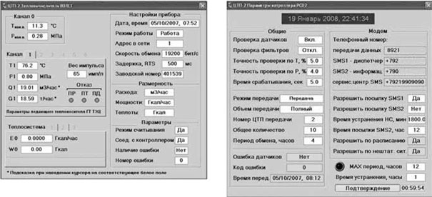
Rice. 2. Control screens for the Vzlet TSRV heat calculator and PCD253 controller
On fig. 3 shows pop-up panels for control equipment (control valve and pump groups). It displays the current status of this equipment, error details and some parameters needed for self-diagnosis and verification. So, for pumps, dry-running pressure, MTBF and start-up delay are very important parameters.

Rice. 3. Control panel for pump groups and control valve
On fig. 4 shows screens for monitoring parameters and control loops in graphical form with the ability to view the history of changes. All controlled parameters of the heat substation are displayed on the parameters screen. They are grouped according to their physical meaning (temperature, pressure, flow, amount of heat, heat output, lighting). All control loops with parameters are displayed on the screen of control loops and displayed present value parameter, given taking into account the dead zone, the position of the valve and the selected control law. All this data on the screens is divided into pages, similar to the generally accepted design in Windows applications.

Rice. 4. Screens for graphic display of parameters and control loops
All screens can be moved across the space of two monitors while performing multiple tasks at the same time. All necessary parameters for trouble-free operation of the heat distribution system are available in real time.
How long has the system been in development?how many developers were there?
The basic part of the dispatching and control system in Trace Mode was developed within one month by the author of this article and launched in the city of Velsk. On fig. a photograph is presented from the temporary control room, where the system is installed and is undergoing trial operation. At the moment, our organization is putting into operation one more heating point and an emergency source of heat. It is at these facilities that a special control room is being designed. After its commissioning, all eight heat points will be included in the system.

Rice. five. Temporary dispatcher's workplace
During the operation of the automated process control system, various comments and wishes from the dispatching service arise. Thus, the process of updating the system is constantly underway to improve the operational properties and convenience of the dispatcher.
What is the effect of introducing such a management system?
Advantages and disadvantages
In this article, the author does not set the task of assessing the economic effect of the introduction of a management system in numbers. However, the savings are obvious due to the reduction of personnel involved in the maintenance of the system, a significant reduction in the number of accidents. In addition, the environmental impact is obvious. It should also be noted that the introduction of such a system allows you to quickly respond and eliminate situations that may lead to unforeseen consequences. The payback period for the entire complex of works (construction of a heating main and heating points, installation and commissioning, automation and dispatching) for the customer will be 5-6 years.
The advantages of a working control system can be given:
Visual presentation of information on the graphic image of the object;
As for the animation elements, they were added to the project in a special way to improve the visual effect of viewing the program.
Prospects for the development of the system