Release headline. “Waste water discharge. The materials below are provided for informational use only. The company is not currently engaged in the sale of equipment and other materials.
The page you requested is under reorganization.
We bring to your attention a new service for owners and managers of small and medium-sized enterprises, individual entrepreneurs: "Improving the profitability of small and medium-sized businesses by reducing unproductive costs and increasing labor productivity!!! Increasing the profitability of the business as a whole." .
Health. Yours. your loved ones. How are you feeling? Do you have chronic diseases? Chronic fatigue? Not much, but often sick (at the same time, the temperature often does not exceed 37 degrees)? Or just want to lead an active lifestyle and prolong active longevity!!! In this case, we recommend that you familiarize yourself with the section of our website dedicated to restoring the body's immune system!!! She needs your help!!! Help her!!! She will do wonders!
The materials below are posted
for informational use only.
Sale of equipment and other materials
the company is not currently engaged
!!!
Steam meters, gas meters (LLC "TIRES"). .
Equipment for protection systems electrical networks, automation and control from the company NPP Novatek-Electro.
general informationWater outlet from reinforced concrete pipes Du500 mm; Hmax = 5.0 m; Qmax = 0.85 cu. m/s. General form. Section 1-1. Plan
Water outlet from reinforced concrete pipes Du500 mm; Hmax = 8.0 m; Qmax = 1.00 cu. m/s. General form. Section 1-1. Plan
Water outlet from reinforced concrete pipes Du500 mm; Hmax = 12.0 m; Qmax = 1.10 cu. m/s. General form. Section 1-1. Plan
Water outlet from reinforced concrete pipes Du500 mm; Hmax = 5.0…12.0 m. General view. Cuts 2-2 - 5-5
Water outlet from reinforced concrete pipes Du600 mm; Hmax = 5.0 m; Qmax = 1.20 cu. m/s. General form. Section 1-1. Plan
Water outlet from reinforced concrete pipes Du600 mm; Hmax = 8.0 m; Qmax = 1.40 cu. m/s. General form. Section 1-1. Plan
Water outlet from reinforced concrete pipes Du600 mm; Hmax = 12.0 m; Qmax = 1.60 cu. m/s. General form. Section 1-1. Plan
Water outlet from reinforced concrete pipes Du600 mm; Hmax = 5.0…12.0 m. General view. Cuts 2-2 - 5-5
Outlet from steel pipes DN300 mm; Hmax = 5.0 m; Qmax = 0.25 cu. m/s. General form. Section 1-1. Plan
Water outlet from steel pipes Du300 mm; Hmax = 8.0 m; Qmax = 0.30 cu. m/s. General form. Section 1-1. Plan
Water outlet from steel pipes Du300 mm; Hmax = 12.0 m; Qmax = 0.35 cu. m/s. General form. Section 1-1. Plan
Water outlet from steel pipes Du300 mm; Hmax = 5.0…12.0 m. General view. Sections 2-2 - 3-3. Fragment 1
Water outlet from steel pipes Du400 mm; Hmax = 5.0 m; Qmax = 0.45 cu. m/s. General form. Section 1-1. Plan
Water outlet from steel pipes Du400 mm; Hmax = 8.0 m; Qmax = 0.55 cu. m/s. General form. Section 1-1. Plan
Water outlet from steel pipes Du400 mm; Hmax = 12.0 m; Qmax = 0.60 cu. m/s. General form. Section 1-1. Plan
Water outlet from steel pipes Du400 mm; Hmax = 5.0…12.0 m. General view. Sections 2-2 - 3-3. Fragment 1
Water outlet from steel pipes Du600 mm; Hmax = 8.0 m; Qmax = 1.30 cu. m/s. General form. Section 1-1. Plan
Water outlet from steel pipes Du600 mm; Hmax = 12.0 m; Qmax = 1.50 cu. m/s. General form. Section 1-1. Plan
Water outlet from steel pipes Du600 mm; Hmax = 8.0…12.0 m. General view. Cuts 2-2 - 3-3
Water outlet from reinforced concrete pipes Du500 - 600 mm. Input heads ORm5, ORm6. General form
Water outlet from reinforced concrete pipes Du500 - 600 mm. Input heads ORm5, ORm6. Knots
Water outlet from reinforced concrete pipes Du500 mm. Entrance cap ORm5. Specification
Water outlet from reinforced concrete pipes Du600 mm. Entrance cap ORm6. Specification
Water outlet from reinforced concrete pipes Du500 mm. Entrance cap ORm5. Reinforcement scheme
Water outlet from reinforced concrete pipes Du600 mm. Entrance cap ORm6. Reinforcement scheme
Water outlet from reinforced concrete pipes Du500 mm. diaphragms. Foundations for the pipeline. General views
Water outlet from reinforced concrete pipes Du500 mm. Foundation for pipeline OBm5. Reinforcement scheme
Water outlet from reinforced concrete pipes Du500 mm. Diaphragm Dm5-1. Reinforcement scheme
Water outlet from reinforced concrete pipes Du500 mm. Diaphragm Dm5-2. Reinforcement scheme
Water outlet from reinforced concrete pipes Du600 mm. diaphragms. Foundations for the pipeline. General views
Water outlet from reinforced concrete pipes Du600 mm. Foundation for pipeline OBm6. Reinforcement scheme
Water outlet from reinforced concrete pipes Du600 mm. Diaphragm Dm6-1. Reinforcement scheme
Water outlet from reinforced concrete pipes Du600 mm. Diaphragm Dm6-2. Reinforcement scheme
Water outlets from reinforced concrete pipes Du500 and 600 mm. Details of pipeline structures made of reinforced concrete pipes
Water outlets from reinforced concrete pipes Du500 and 600 mm. Output heads. General views
Water outlet from reinforced concrete pipes Du500 mm. Output head OVm5. Reinforcement scheme
Water outlet from reinforced concrete pipes Du600 mm. Output head OVm6. Reinforcement scheme
Water outlet from steel pipes Du300, 400 and 600 mm. Input heads OP3, OP4, OP6. General form
Water outlet from steel pipes Du300, 400 and 600 mm. Input heads OP3, OP4, OP6. Knots
Water outlets from steel pipes Du300 and 400 mm. Input heads OP3 and OP4. Reinforcement scheme
Water outlet from steel pipes Du600 mm. Entrance head OP6. Reinforcement scheme
Umbrella heads 03-1, 03-2. Assembly drawing
Umbrella heads 03-3, 03-4. Assembly drawing
Umbrella head 03-4. Specification
Umbrella head 03-5. Specification
Umbrella head 03-5. Assembly drawing
Umbrella head 03-6. Assembly drawing
Umbrella head 03-7. Specification
Umbrella head 03-8. Specification
Umbrella head 03-7. Assembly drawing
Umbrella head 03-8. Assembly drawing
Water outlets from steel pipes Du300 and 400 mm. diaphragms. General views
Water outlets from steel pipes Du600 mm. diaphragms. General views
Water outlets Du500 and 600 mm. Wells K-1, K-1A, K-2, K-2A. Specification
Water outlets Du500 and 600 mm. Wells K-1, K-1A, K-2, K-2A. General form. Plan. Nodes 2 - 4
Water outlets Du500 and 600 mm. Wells K-1, K-1A, K-2, K-2A. General form. Section 1-1. Node 1
Water outlets Du500 and 600 mm. Wells K-1, K-1A, K-2, K-2A. General form. Cuts 2-2 - 6-6
Water outlets from steel pipes Du300 and 400 mm. Wells K-3, K-3A. Specification
Water outlets from steel pipes Du300 and 400 mm. Wells K-3, K-3A. General form. Section 1-1. Plan
Water outlets from steel pipes Du300 and 400 mm. Wells K-3, K-3A. General form. Sections 2-2 - 4-4. Knots
Well K-4. General form
Water outlets from steel pipes Du600 mm. Output cap. Specification
Water outlets from steel pipes Du600 mm. Outlet head supported by reinforced concrete piles. General form. Option 1
Water outlets from steel pipes Du600 mm. Outlet cap with steel pipe support. General form. Option 2
Water outlets from steel pipes Du300 mm. Output cap. Specification
Water outlets from steel pipes Du400 mm. Output cap. Specification
Water outlets from steel pipes Du300 mm. Output cap. General form
Water outlets from steel pipes Du400 mm. Output cap. General form
Winter branch of the pipeline at Hz1 > 2.0 m. Specification
< 2,0 м. Спецификация
Winter branch of the pipeline at Hz1 =< 2,0 м
Winter branch of the pipeline at Hz1 > 2.0 m
Water outlets from reinforced concrete pipes Du500 and 600 mm. End section of water outlet with outlet cap OVUm5
Water outlets from reinforced concrete pipes Du500 and 600 mm. Output head OVUm5. Specification
Water outlets from reinforced concrete pipes Du500 mm. Output head OVUm5. General form
Water outlets from reinforced concrete pipes Du500 mm. Output head OVUm5. Reinforcement scheme. Cuts 1-1 - 3-3
Water outlets from reinforced concrete pipes Du500 mm. Output head OVUm5. Reinforcement scheme. Cuts 4-4 - 9-9
Water outlets from reinforced concrete pipes Du600 mm. Output head OVUm6. Specification
Water outlets from reinforced concrete pipes Du600 mm. Output head OVUm6. General form
Water outlets from reinforced concrete pipes Du600 mm. Output head OVUm6. Reinforcement scheme. Cuts 1-1 - 3-3
Water outlets from reinforced concrete pipes Du600 mm. Output head OVUm6. Reinforcement scheme. Cuts 4-4 - 9-9
Reinforcing mesh C1
Reinforcing mesh C2, C3
Reinforcing mesh С4
Reinforcing mesh C5
Reinforcing mesh C6
Reinforcing mesh С7
Reinforcing meshes С8, С8Н
Reinforcing mesh С9, С9Н
Reinforcing mesh C10, C11
Reinforcing mesh C12
Reinforcing mesh С13
Reinforcing mesh С14
Reinforcing mesh С15
Reinforcing mesh С16
Reinforcing mesh С17
Reinforcing mesh С18
Reinforcing mesh С19
Reinforcing mesh С20
Reinforcing mesh С21
Reinforcing mesh С22, С23
Reinforcing mesh С24
Reinforcing mesh С25
Reinforcing mesh С26
Reinforcing mesh С27
Reinforcing mesh С28
Reinforcing mesh С29
Reinforcing mesh С30
Reinforcing mesh С31
Reinforcing mesh C32
Reinforcing mesh С33
Reinforcing mesh С34, С35
Mortgage product M1
Mortgage product M2
Mortgage product M3
Head blocks are important components of culverts that close its body. These devices, regardless of the geometric shape, perform a number of identical functions. Firstly, they contribute to the uniform inflow and outflow of waters of various origins. Secondly, they have a strengthening function, supporting the slopes of embankments. An important task is to protect the entrance and exit clearance of the structure from clogging with soil.
Heads determine the mode of hydraulic operation of the pipeline: pressure, semi-pressure and non-pressure. There is an inlet section, located on the upper side of the embankment, and an outlet section, located on the downstream side. By design, the head parts are classified into: portal, corridor, socket, collar, streamlined.
Portal heads have the simplest structure. They are presented in the form of a retaining block necessary to maintain the slope of the road embankment. With respect to the longitudinal axis of the pipe, the wall is installed perpendicularly. This design is suitable for low flow rates and low flow rates.
A feature of the corridor head is parallel blocks deployed at their beginning, the height of which is constant.
The socket head includes a portal wall block and sloping wings. Such a structure improves the conditions for the flow of fluid. The device is designed to operate pipes in non-pressure and pressure modes. Socket heads in combination with elevated links are installed in rectangular pipes, and in combination with conical ones - for round ones.
Collar heads are elliptical end links located in the plane of the slope of the embankment.
In the form of a truncated pyramid, a streamlined head is made. Its complex design allows the pipeline to function effectively in floods with a full cross section. These heads are suitable for the installation of round pressure pipes.
AT standard projects pipe designs are provided for operation in different modes, as well as for areas of permafrost, ice formation and on slopes. Based on the calculations of the strength of the water flow, its width, frequency, as well as on the characteristics of the soil, a suitable head shape is chosen. The width of the tip, corresponding to the watercourse, captures the flow of water and prevents erosion of a significant part of the road embankment.
The ZHBI MARKET plant successfully carries out sale of reinforced concrete heads. The production of head blocks is based on various standard projects. It is possible to manufacture reinforced concrete products according to working documentation provided by customers. You can buy products from the manufacturer for equipping road facilities in St. Petersburg and other regions at affordable prices.
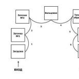
K category: cleaning Wastewater
Discharge of wastewater into a reservoir
Purified wastewater during artificial treatment is diverted through the channel to the place of their descent into the reservoir. The outlet channel usually ends with a coastal well, from which the treated wastewater is discharged through the outlet into the reservoir. The more favorable the conditions for mixing the discharged wastewater with the waters of the reservoir, the better the self-cleaning ability of the reservoir is used, the more polluted wastewater can be discharged into it.
Wastewater outlets are classified by the type of water body (river, lake and sea), by location (coastal, channel and deep) and by design (concentrated and dissipating).
Coastal concentrated releases are designed in the form of open channels, fast currents, cantilever discharges, heads. In this case, there is a very slight dilution of the discharged wastewater with the water of the reservoir, so the use of the self-cleaning capacity of reservoirs is very low. Such outlets are used to discharge rainwater or lightly polluted wastewater. More often, channel dissipating outlets are arranged, providing the best mixing of wastewater with river water. Deep outlets are used when discharging wastewater into lakes, reservoirs, and seas.
The outlet is a steel perforated pipe with a metal clip with slots. The clip is filled with gravel or crushed stone. The area of the slotted holes of the cage bottom is 40-50% of its area. The exit of water in the form of vertical jets ensures effective mixing with the water of the reservoir.
Part 2
Treated wastewater is discharged through the channel to the place of their descent into the reservoir. The outlet channel usually ends with a coastal well, from which treated wastewater is discharged into a reservoir through the so-called outlet. The design of the outlet is essential to address the issue of the required degree of wastewater treatment. The more favorable the conditions for mixing the discharged water with the water of the reservoir, the more the self-cleaning capacity of the reservoir is used, the lower the required degree of wastewater treatment. Distinguish the following designs of outlets: concentrated, through which water is discharged into the reservoir through only one hole; scattering, in which water is discharged through a series of holes. In practical conditions, both outlets are used, but the scattering outlet is more common, since it provides better mixing of wastewater with reservoir water.
Rice. 1. Diffusion outlet with tees and elbows

Rice. 2. General view of the scattering outlet
The outlet should be brought to the middle of the river. In the place where the release is laid, the river bottom must be protected from erosion and silting.
The choice of a place for the discharge of treated wastewater should be agreed with the sanitary inspection authorities, shipping departments and other organizations that are interested in maintaining the conditions for the normal operation of the reservoir.
Currently, in most cases, the following designs of scattering sewer outlets are used: outlets with tees and elbows (Fig. 1) and with tees (Fig. 2).
On fig. 2 shows a general view of the dissipative outlet of the Giprospetsneft design with water distribution through tees.
AT recent times eng. A. Kh. Maksimov. (Leningrad) proposed a simplified design of the scattering outlet, which provides good operating conditions. Water is released through holes in the pipe, located at a certain distance from each other.
Eng. A. Kh. Maksimov also developed a theory of hydraulic calculation of such an outlet, based on the fact that with the gradual distribution of water through the holes, the so-called movement of a fluid with a variable mass takes place.
- Discharge of sewage into a reservoir
→ Water intake and treatment facilities
Heads of sewer outlets
Industrial and municipal wastewater discharged into rivers, lakes, reservoirs and seas significantly change the regime of the aquatic environment, disrupting the vital activity of vengeful and animal organisms.
Water pollution and self-purification are two interrelated processes resulting from economic activity human, as well as due to the natural flow of polluted effluents into watercourses and reservoirs. These processes are greatly influenced by the dilution regimes of wastewater, which are determined by the design and technological features of their discharge, which in turn depend on the hydrometeorological features of water bodies and watercourses.
At the initial stage, the dilution process is largely determined by design features release. Special studies have established that dilution proceeds more intensively with scattering outlets than with concentrated ones. The dilution process is significantly influenced by: the nature of the movement of water masses; the causes that cause these movements are runoff, wind, distribution of temperatures and densities; morphometric characteristics of the channel of the watercourse or the bed of the reservoir; degree of flow; composition and properties of the environment.
The flow of watercourses is always turbulent and is determined by the morphological features of the banks and the bed of the river: the indentation of the coastline, islands, rifts, gorges and rapids. The efficiency of water mixing depends on the impact of these factors on the flow dynamics, leading to the fragmentation of the established flow structure and the formation of eddies.
In reservoirs (lakes, reservoirs, seas), various kinds of currents are observed, which are formed as a result of the influence of several factors. The main ones for our northern seas (Baltic, White, etc.), which deeply cut into the land, as well as lakes and reservoirs, are wind currents, to which runoff currents are added in lakes.
For watercourses (rivers, canals), the design site for drinking and cultural and domestic water use is assigned in accordance with SNiP 11-32-74 at a distance of 1 km upstream (downstream) of the existing or prospective water use point.
In lakes, reservoirs, and seas, currents can carry a mixture of sewage and reservoir water in any direction. In lakes and reservoirs, a permissible distance is set equal to 1 km in any direction from the point of water use, and for the seas - no more than 300 m.
Consider the most characteristic types and designs of sewers. According to the location, the releases are divided into coastal, channel, deep and deep water.
Shore outlets serve only for the discharge of storm and conditionally clean water. Such releases, as a rule, are made in the form of embankments or concrete retaining walls with different height levels of the pipeline outlet.
Channel outlets are a pipeline leading into the riverbed and ending in one or more heads. The heads of the outlet are located in the place of the most intense flow of the river, with outlets installed near the middle of the depth of the channel.
Deep outlets are arranged to discharge wastewater into a lake, reservoir or sea at some distance from
Shores (usually to a depth of 10-15 m). At greater depths, outlets are called deep-sea outlets. The shape of the head should be as simple as possible, the dimensions should be minimal, but ensure stability, its connection with pipelines and waterproofing should be durable. It is recommended that the heads be located, if possible, in an area where they are not exposed to wave impacts. The construction of an underwater pipeline requires special attention, since it is constantly exposed to the dynamic effects of the reservoir, and in the case of release into the sea, also to the chemical effects of sea water.
Various schemes for the design of outlet heads are shown in fig. one.
Round holes in the body of the pipe, which have recently been quite widely used abroad in the construction of outlets, are called diffusers and are considered the most rational. The disadvantage of this tip is the low flow rate along the pipeline, which leads to uneven distribution of costs and uneven dilution of wastewater.
Slits in the body of the pipe - a solution similar to the previous one, but it has an even more uneven initial dilution.
Cylindrical tip with reflector is applicable in conditions where, for hydrological reasons, the outlet pipeline cannot be laid on the bottom. The reflector on the cylindrical tip creates a conical jet, hollow inside. The pressure loss in such a head is higher than in the previous ones, its design is more complicated and expensive.

Rice. 1. Various schemes for the design of outlet heads
a - round holes in the body of the pipe; b - slots in the body of the pipe; c - cylindrical head; g - cylindrical head with a reflector; e - cylindrical head with a confuser; e - head with an ejecting nozzle
A cylindrical head with a confuser is a more advanced design.
The tip with an ejecting nozzle was developed and studied by N. N. Laptev and V. F. Tsvilikov. Structurally head of this type more complex and expensive, which, however, pays off with a high efficiency of wastewater dilution.
The diameter of the pipeline of the distribution part of the outlet must have a constant cross section. The use of telescopic pipelines leads to a very uneven outflow of wastewater in individual sections and is reflected in their dilution.
The outlet diameter is set depending on the design flow rate, flow rate and number of nozzles. The smallest diameter of the outlet should be taken equal to 100 mm. The main task of design is to select the section of the pipeline, providing optimal conditions uniform distribution of costs and prevention of head silting.
An example of an interesting engineering solution is the device of a dissipating cap for the release of treated wastewater from a pulp and paper mill from an aerator pond into the river. Vychegdu. The scattering outlet is made of two strings of steel pipes with a diameter of 2040 mm, a length of 779 m and a scattering head made of two sections of pipes: a diameter of 1420 mm, a length of 22.5 m and a diameter of 1020 mm, a length of 16.5 m. In these sections at an angle of 120 ° branch pipes with a diameter of 200 mm are welded to the direction of wastewater discharge in a checkerboard pattern at a distance of 6.2 m from each other. The nozzles rose 1.5 m above the surface of the pipes. To give greater strength and rigidity to pipes with a diameter of 2040 mm, after 2 m along their outer perimeter, stiffeners from channel No. 16 were welded.
In Pärnu, a 3 km offshore pipeline made of polyethylene pipes with a diameter of 800 mm with a dissipating head made of steel pipes with a diameter of 820X10 mm and a length of 533 m was provided for by the project and made in kind for the removal of wastewater from the head sewerage facilities. 12 branch pipes with a diameter of 100 mm were welded to the head. mm, 10 nozzles with a diameter of 150 mm and a shield gate with a diameter of 800 mm.
To develop an underwater trench with a bottom width of 2.7 m with slopes of 1:2.5, hydraulic elevators and hydraulic monitors were used in the deep section and a rope scraper in the floodplain section. The pipeline was laid on a pre-prepared gravel base with subsequent ballasting, providing a safety factor of 1.4.
Steel and polyethylene pipes were welded into lashes of 500 m on the shore on a specially filled embankment. The lashes were interconnected by metal slip-on couplings and half-couplings. Hydraulic tests for density and strength showed that the joints withstand a pressure of not more than 0.035 MPa. Despite the special strengthening of these joints under water with a cement-sand mortar, it was not possible to withstand the test pressure. As this experience shows, large diameter polyethylene pipes should be connected by welding or flanges.